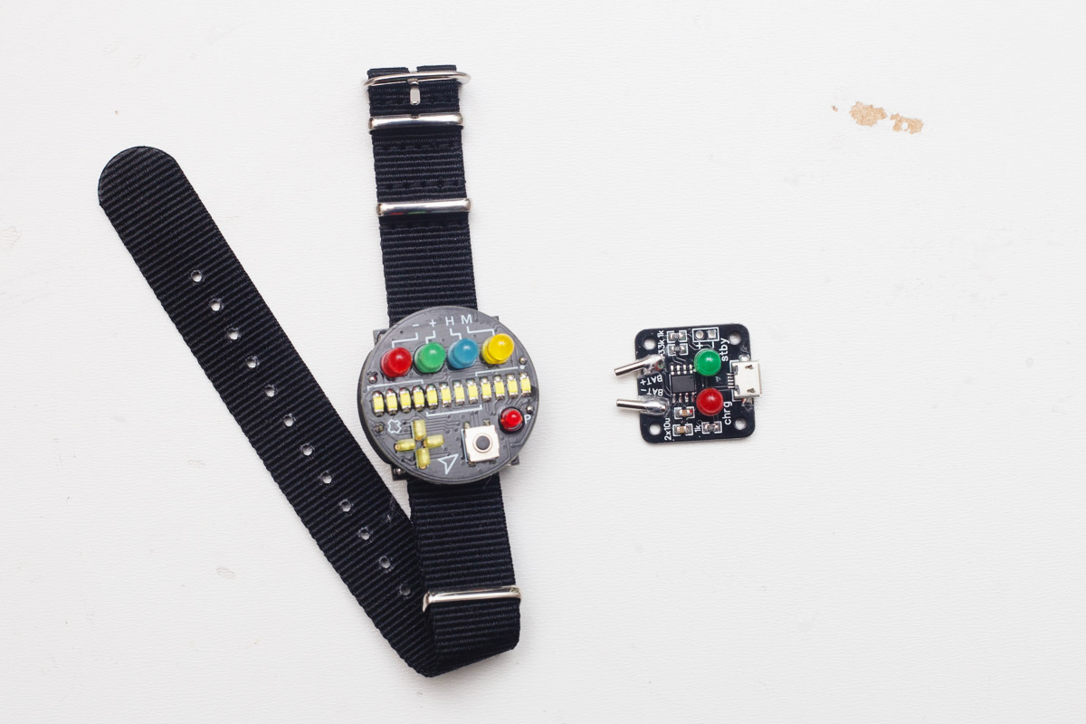
SW63 Build Instructions
Introduction
If you decided to build your own SW63, this step-by-step guide should help you. You can find the schematics on GitHub, but it's not required when following this guide.
The watch is made using very small components, but it's not THAT difficult to solder it. If you haven't soldered SMD stuff before, I would recommend watching some videos how to to that (eg. https://www.youtube.com/watch?v=f9fbqks3BS8).
Disclaimer: I'm a self-taught hobbyist, not a "professional" so if you have better tools or practices, use them as you wish.
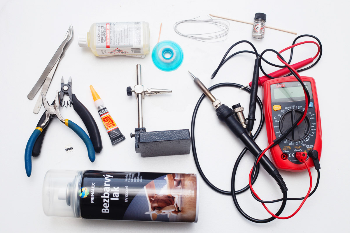
Tools/stuff you will need
- Soldering iron with small tip, solder, flux, solder wick
- Regular pliers, flush cut pliers
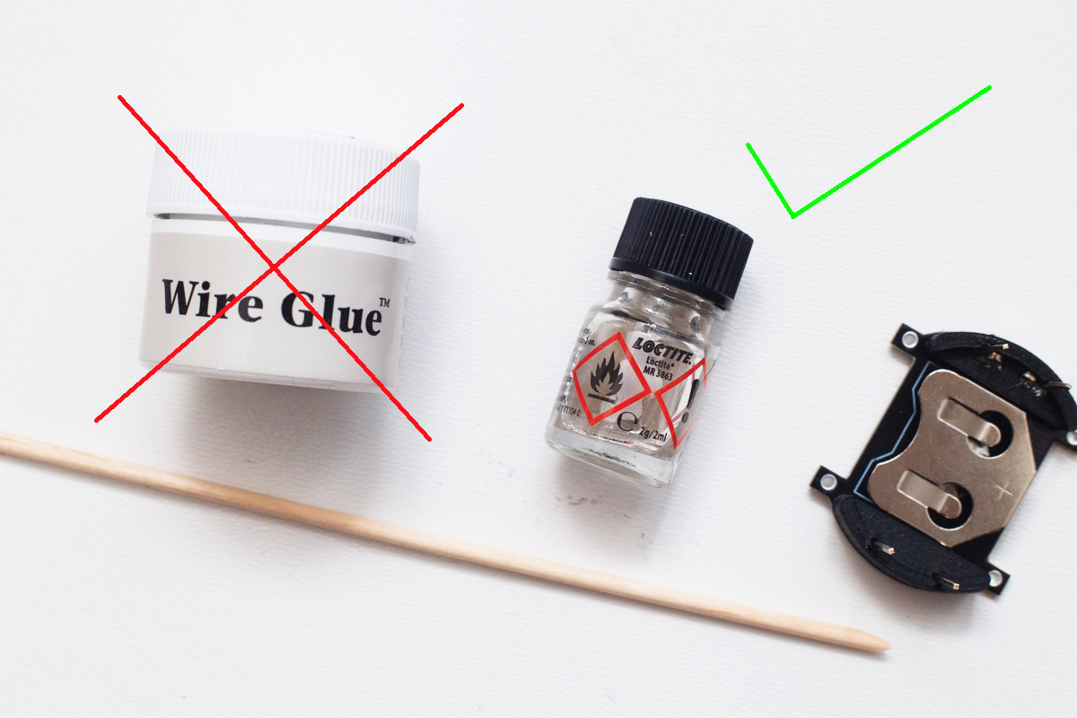
- Super glue
- Helping hands
- Multimeter
- Rubbing alcohol, distilled water, toothbrush for cleaning (not in the picture)
- Clear warnish, four header pins*
- Silver based conductive glue, eg. LOCTITE MR 3863 (used for windshield heating repairs), skewer*
*not required, but highly recommended
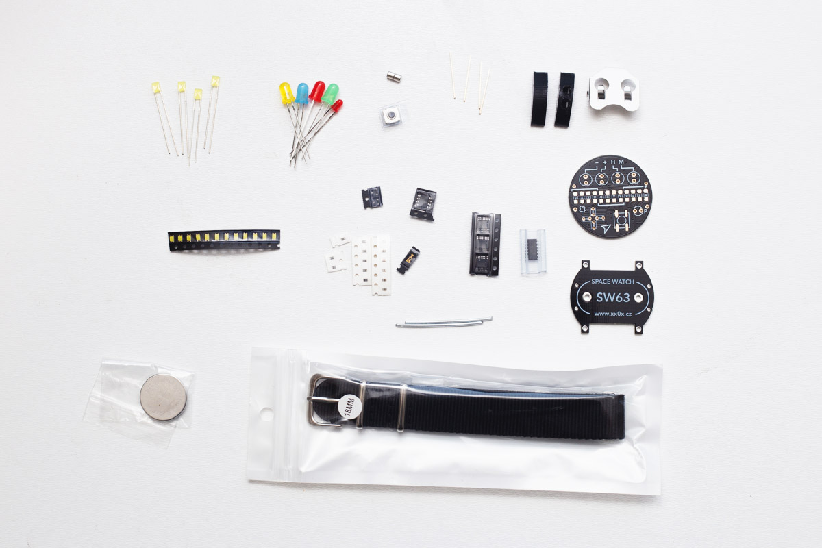
Watch parts
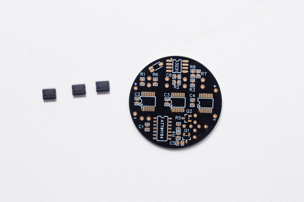
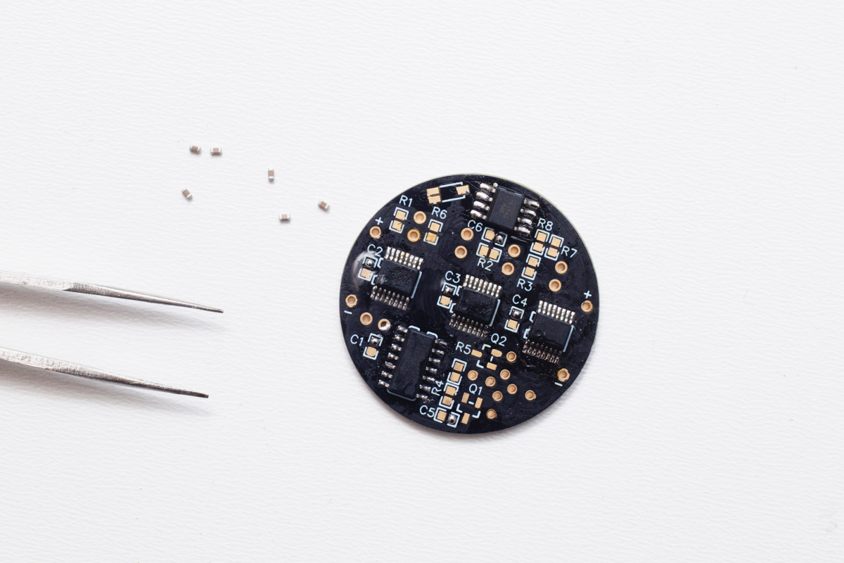
First, pull all watch parts from the bag and sort them on the table.
Building the base
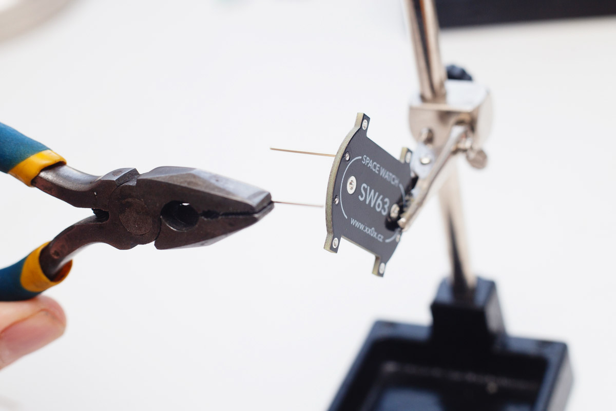
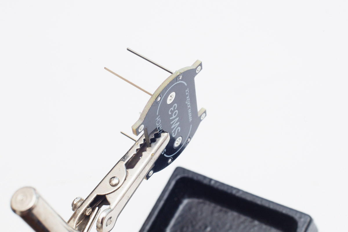
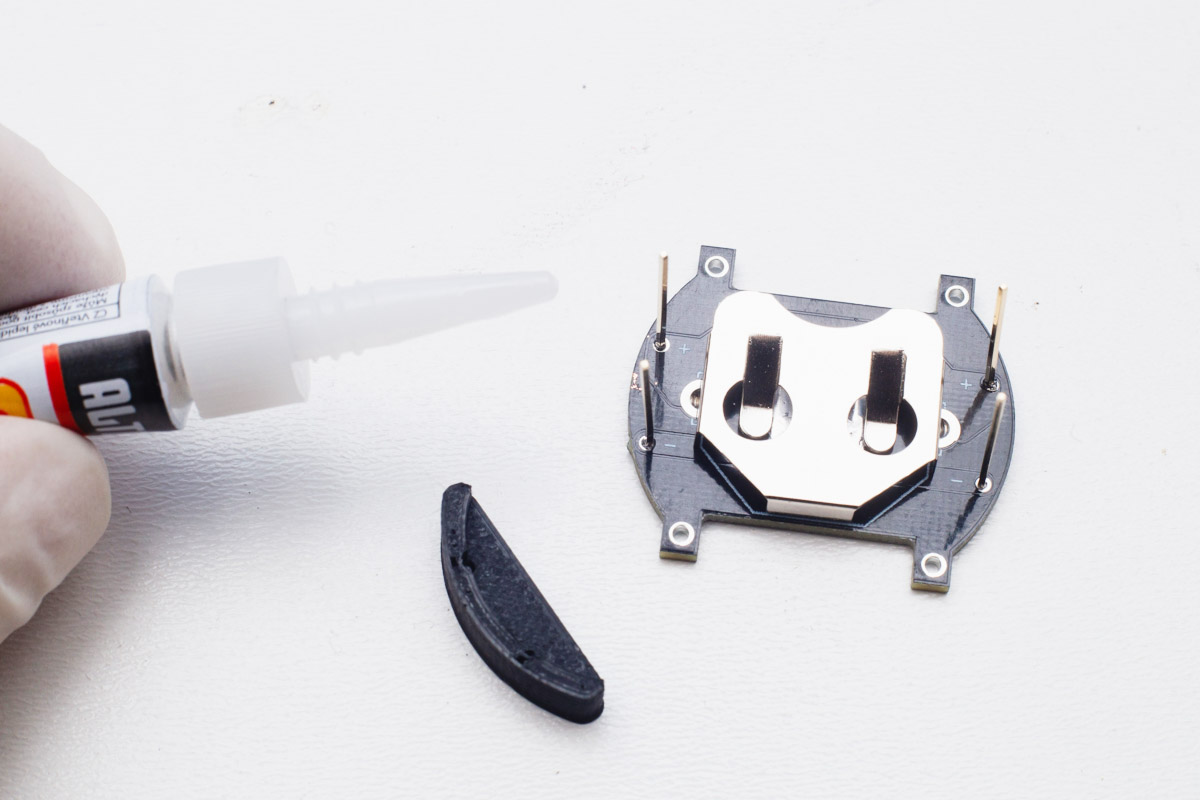
First, mount the base PCB to the helping hands and solder the four support wires. Make sure they are straight and somehow flush with the bottom. When finished, try to fit the two plastic parts onto it (without glue yet).
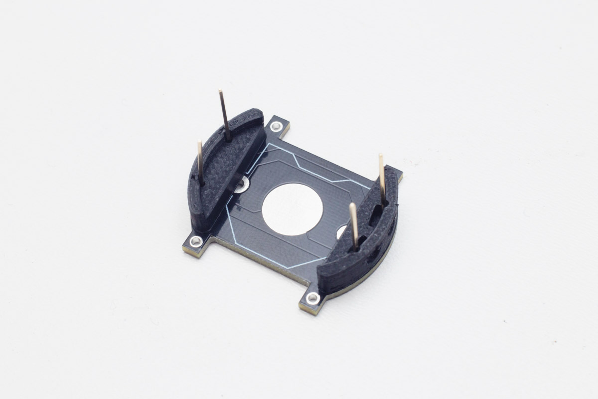
When everything is OK, pull the plastic supports out and solder a little bit of solder to the negative battery contact to improve battery connnection.
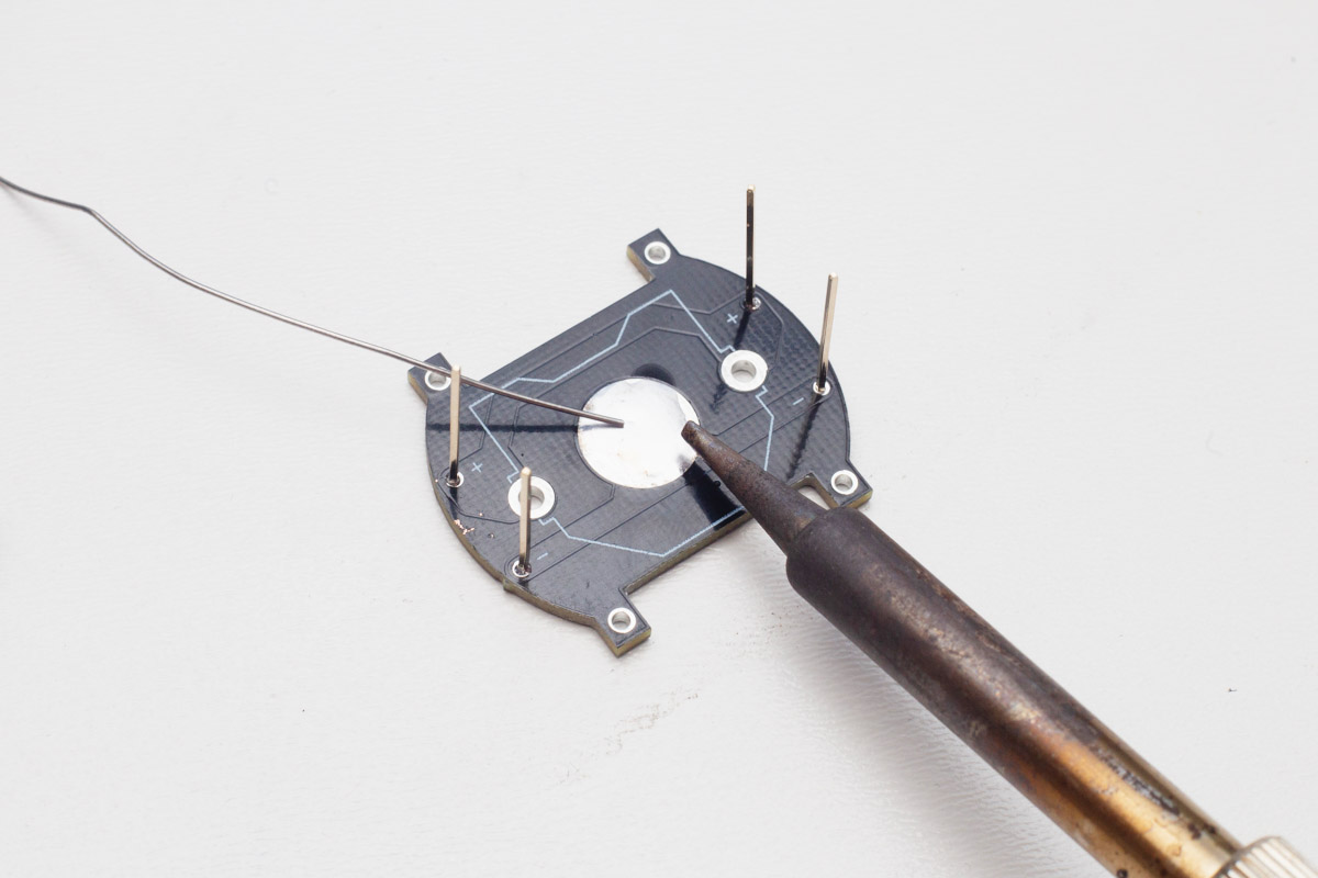
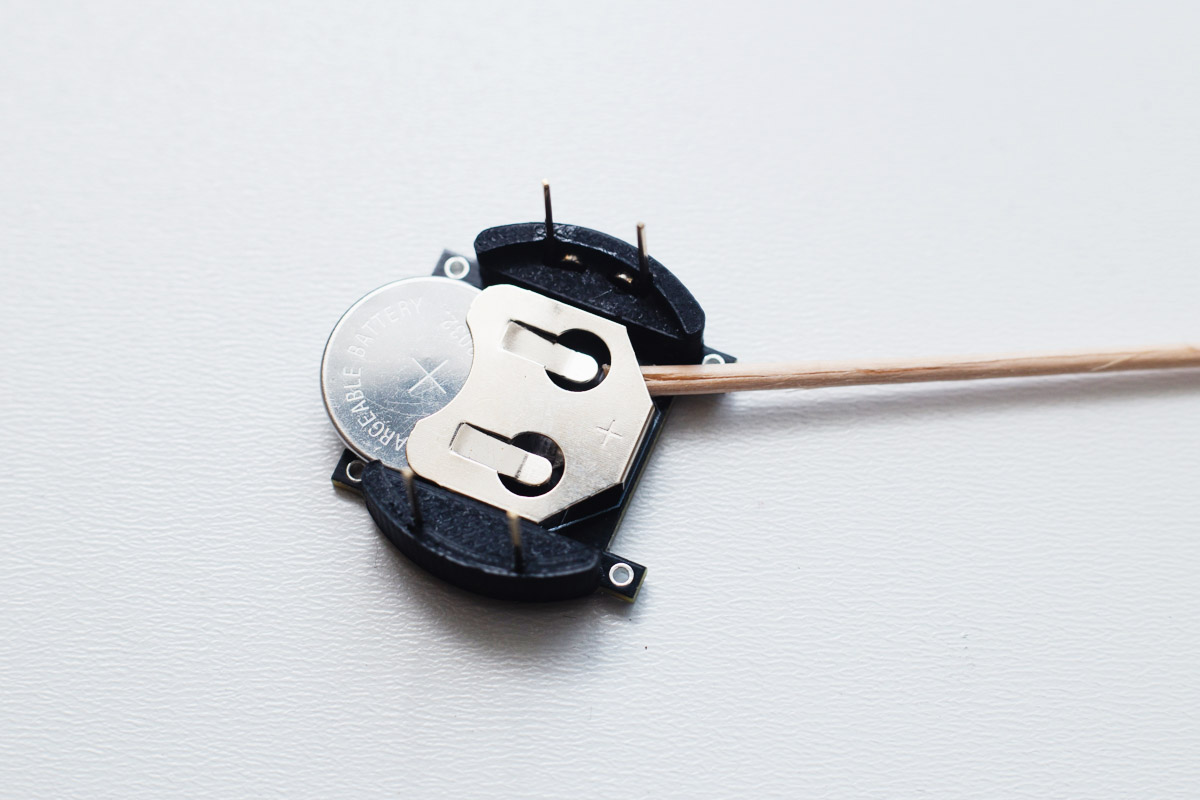
Then solder the battery holder, keep in mind the orientation of it
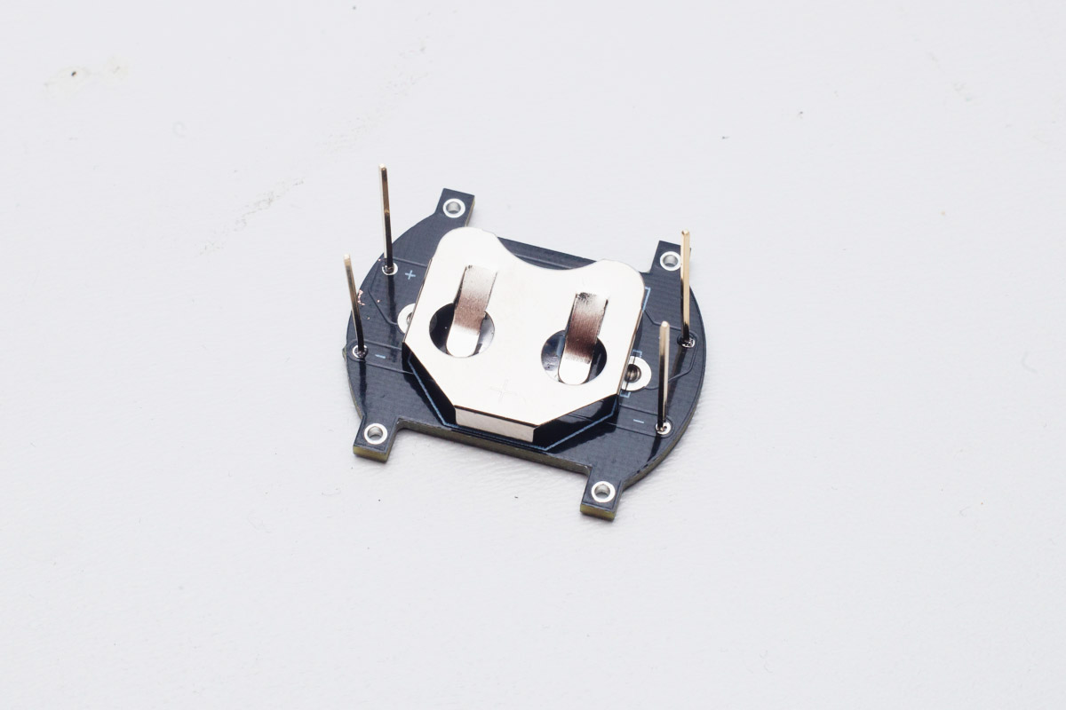

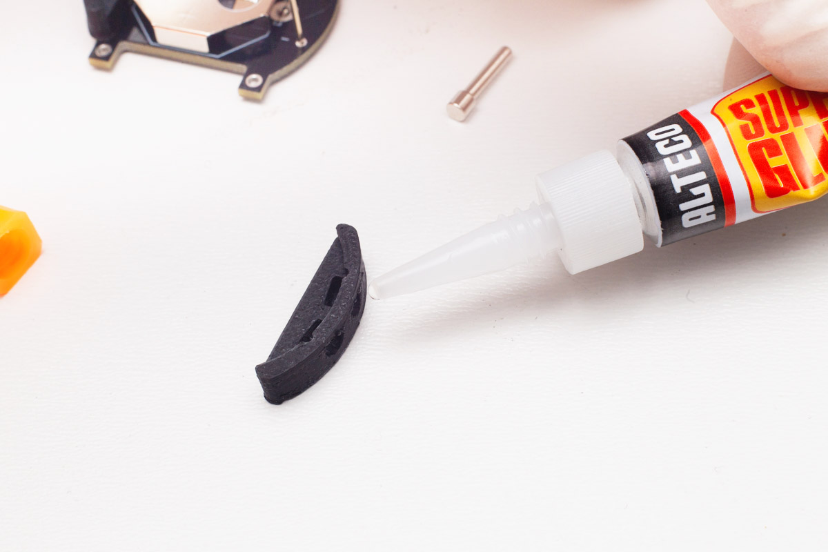
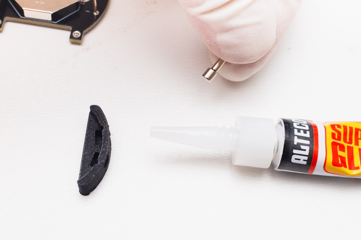
After that, glue the solid plastic part to the left side.
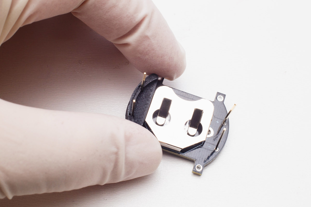
You should end up with something like this.
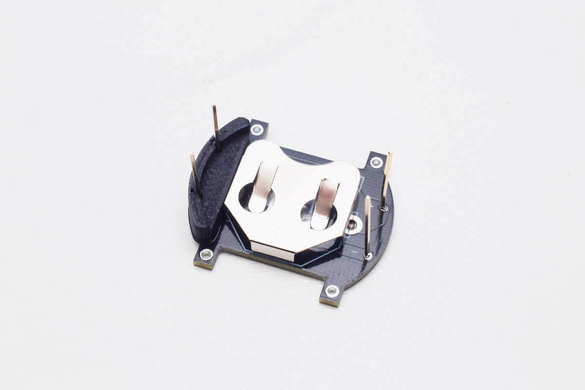
Then, glue the small magnets inside the plastic part with "holes". You can use the magnets from charger as a helping handle. The magnets should be in reversed polarization to each other to prevent wrong connection of the charger, they should also be flush with the outside. The magnet painted black should be on the top.
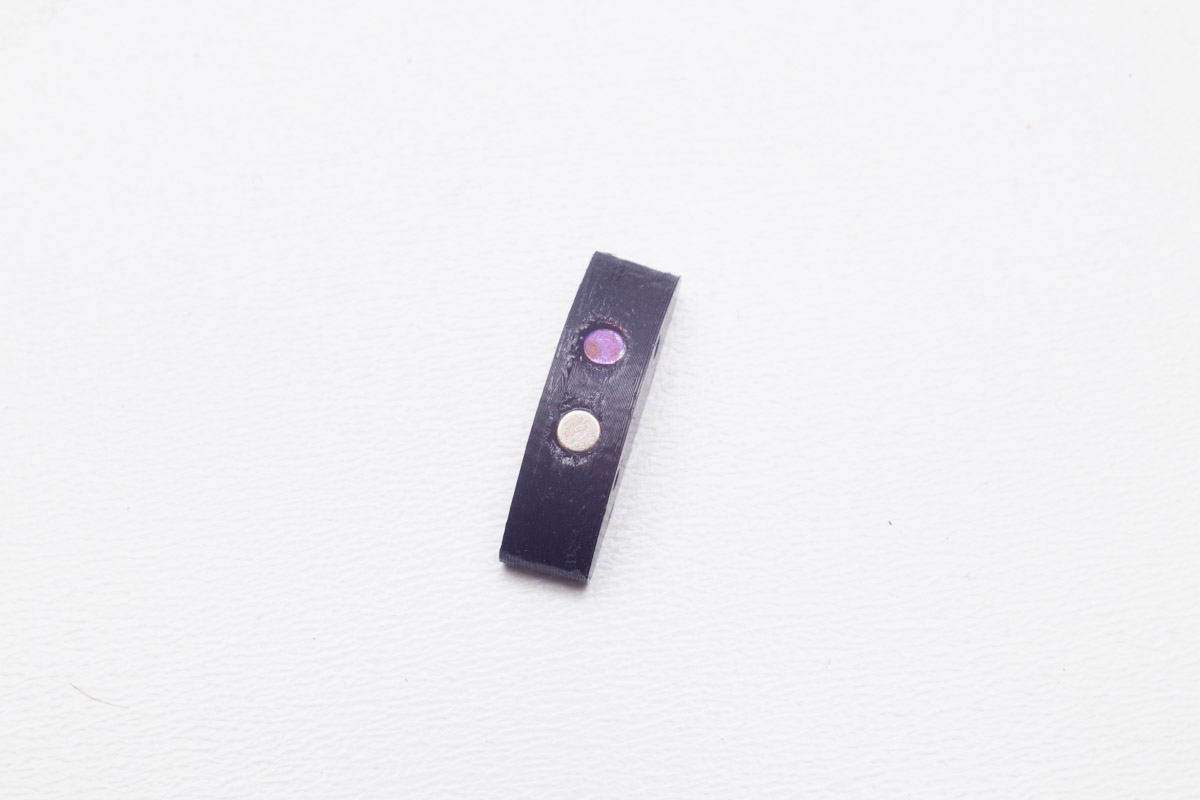

The final result should look like this.

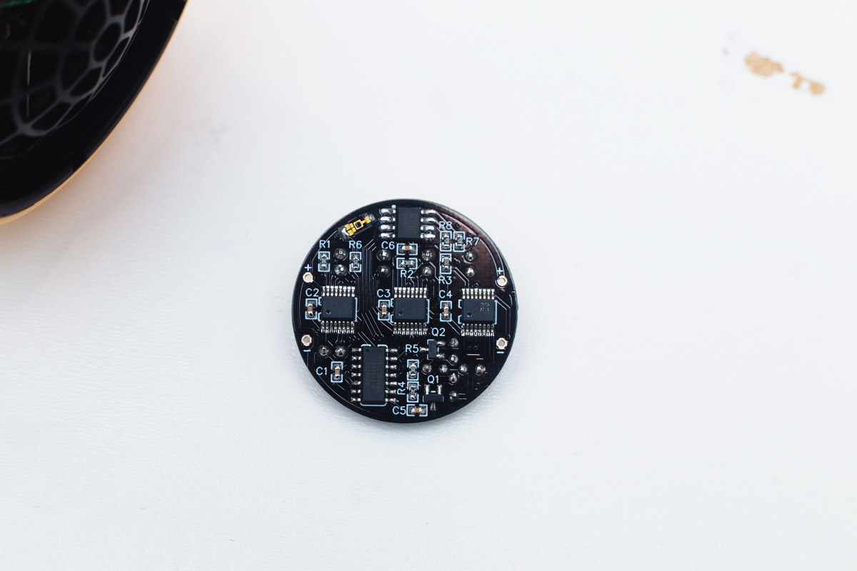
Bottom side of the watchface
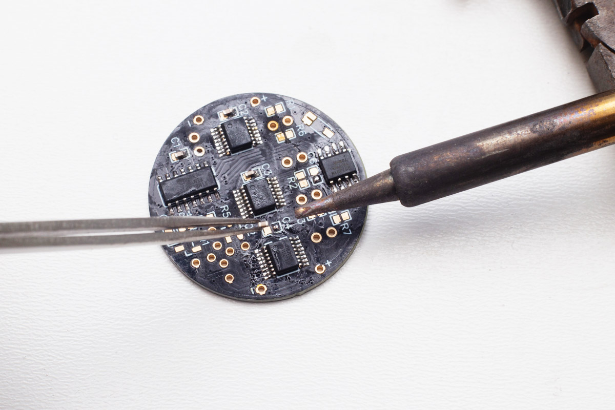
First, start with the LED drivers. Tin one pad, then push the IC into the position while reheating the pad, that's the easiest way of soldering these. Keep the polarity in mind (the dot on the PCB should match the dot on the IC).
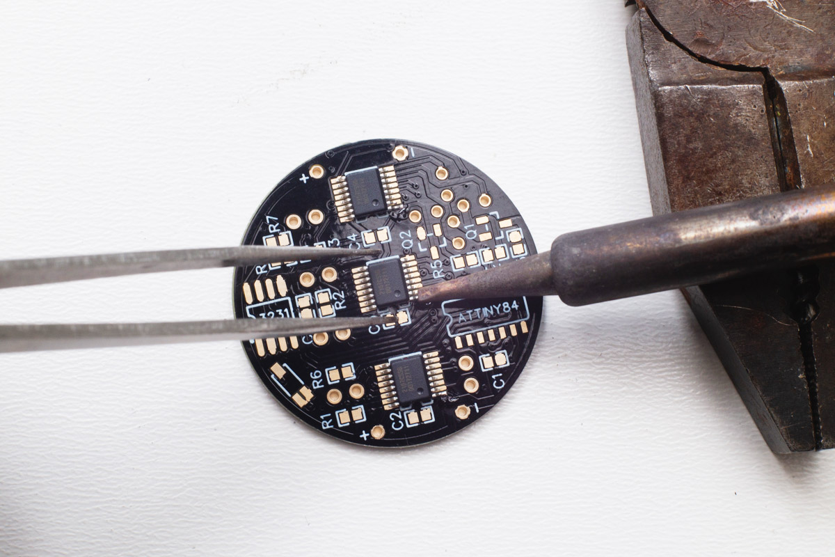
Then, solder all remaining legs. A lot of flux will help you, you can use solder wick to remove the solder bridges.
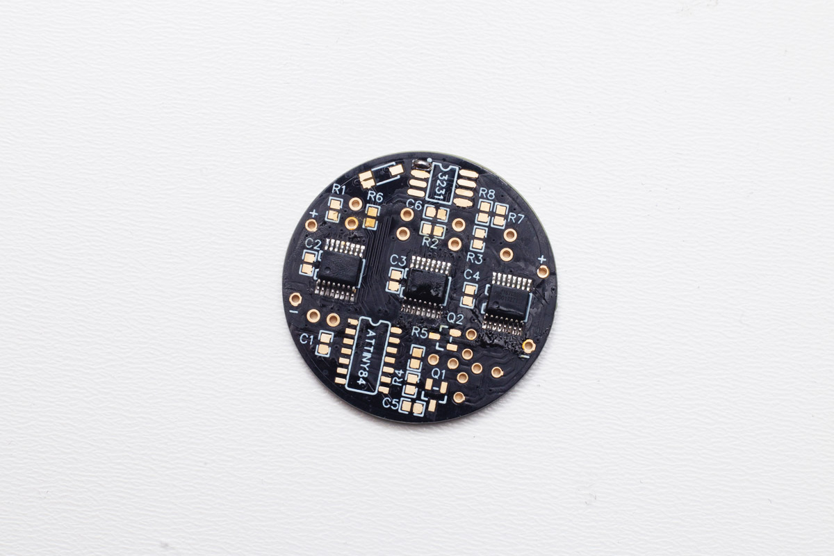
Aftewards, solder the ATtiny microcontroller and RTC chip the same way as the LED drivers.

Solder the six 100n capacitors marked C1–C6 on the PCB. They are all same, the polarity is not important. Again, tin one pad and using pliers solder the capacitor while reheating the pad, then solder the second pad.
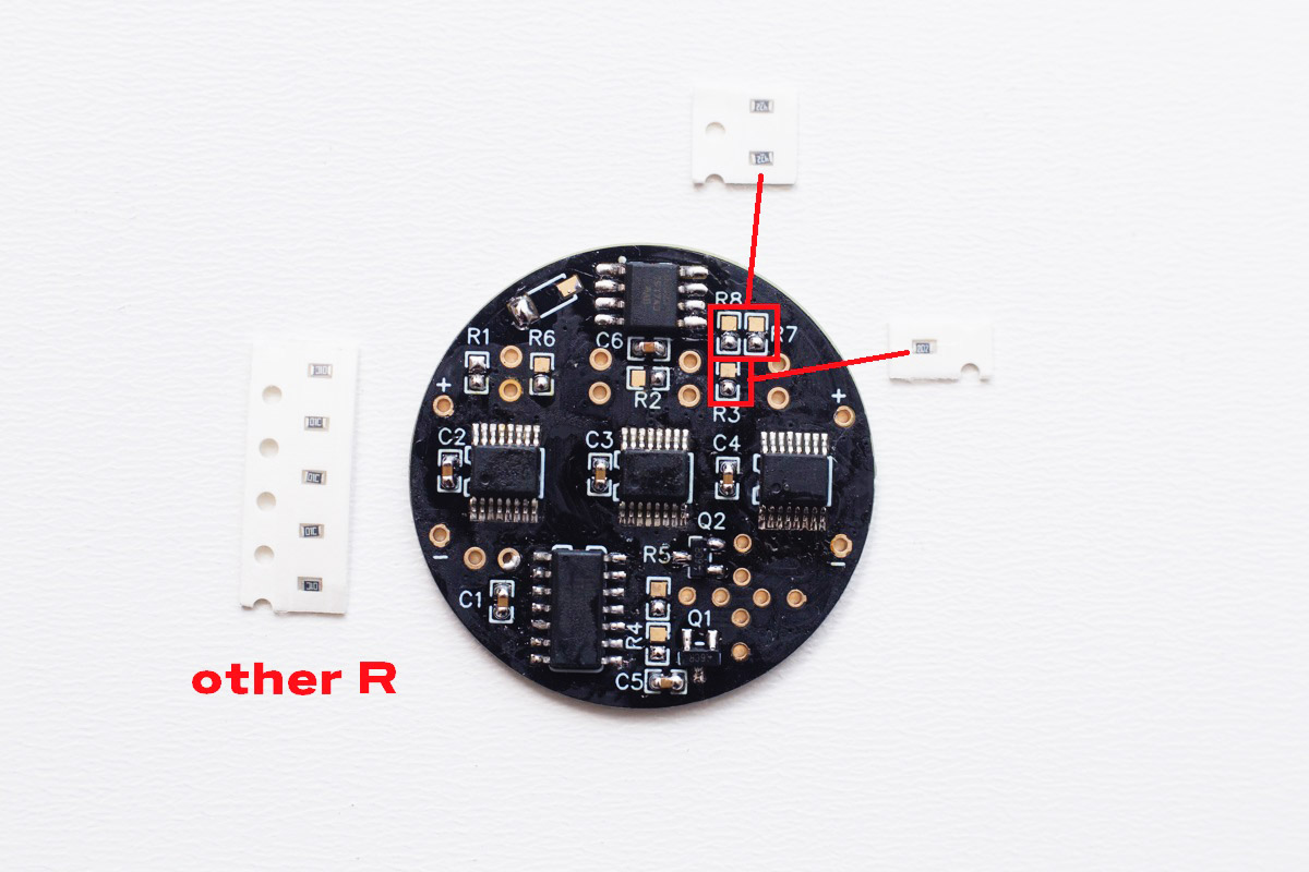
Solder the resistors, R3 is 2k, R7 & R8 are 4k7, the rest are 10k. The polarity doesn't matter.
Now, solder the light sensor using the same practice as before.
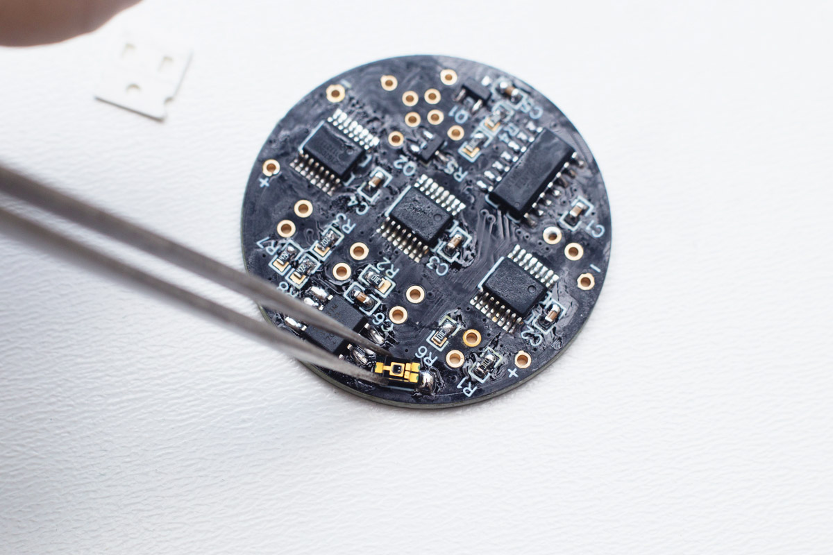
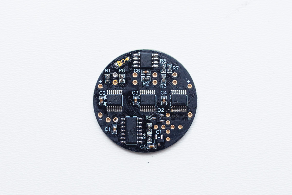
The bottom side should be now complete, check all solder points.
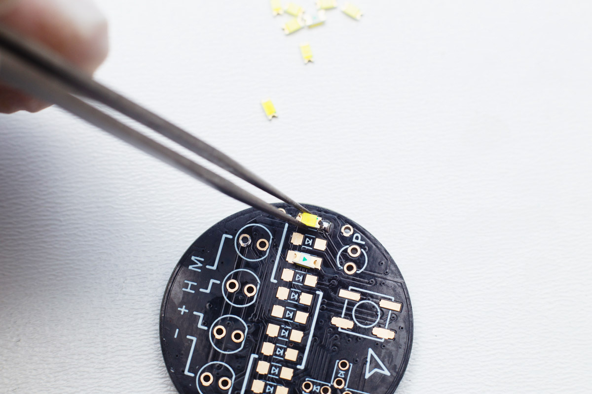
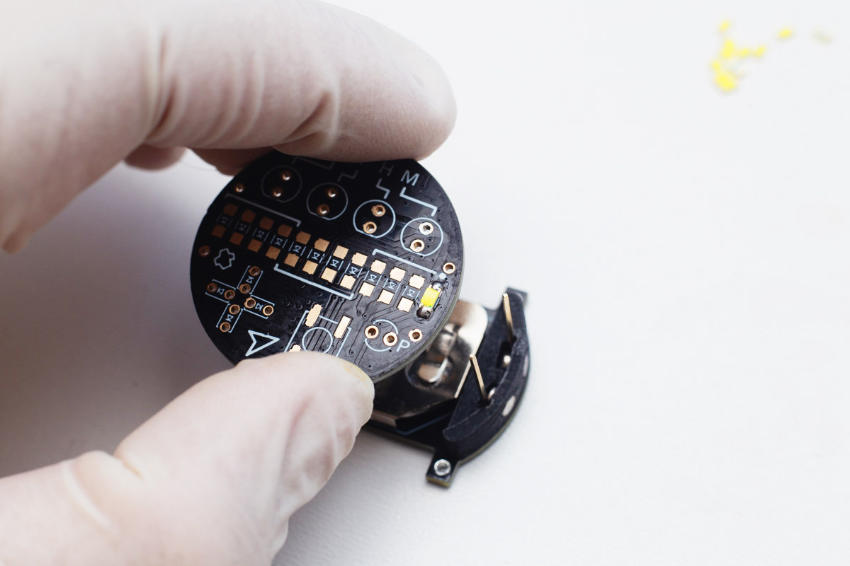
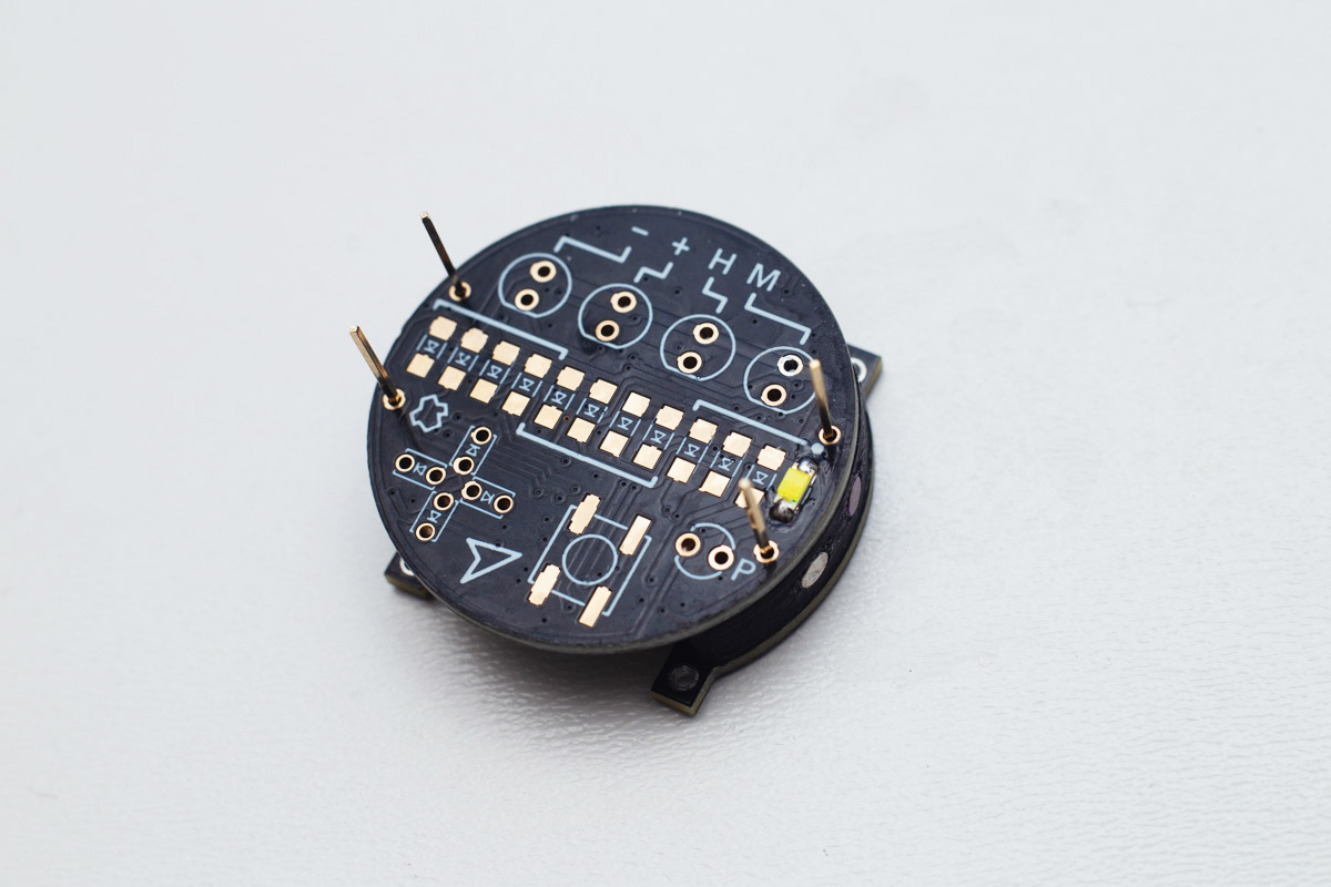
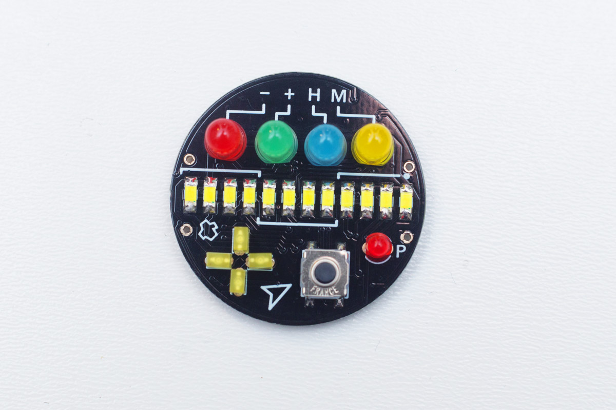
Top side of the watchface
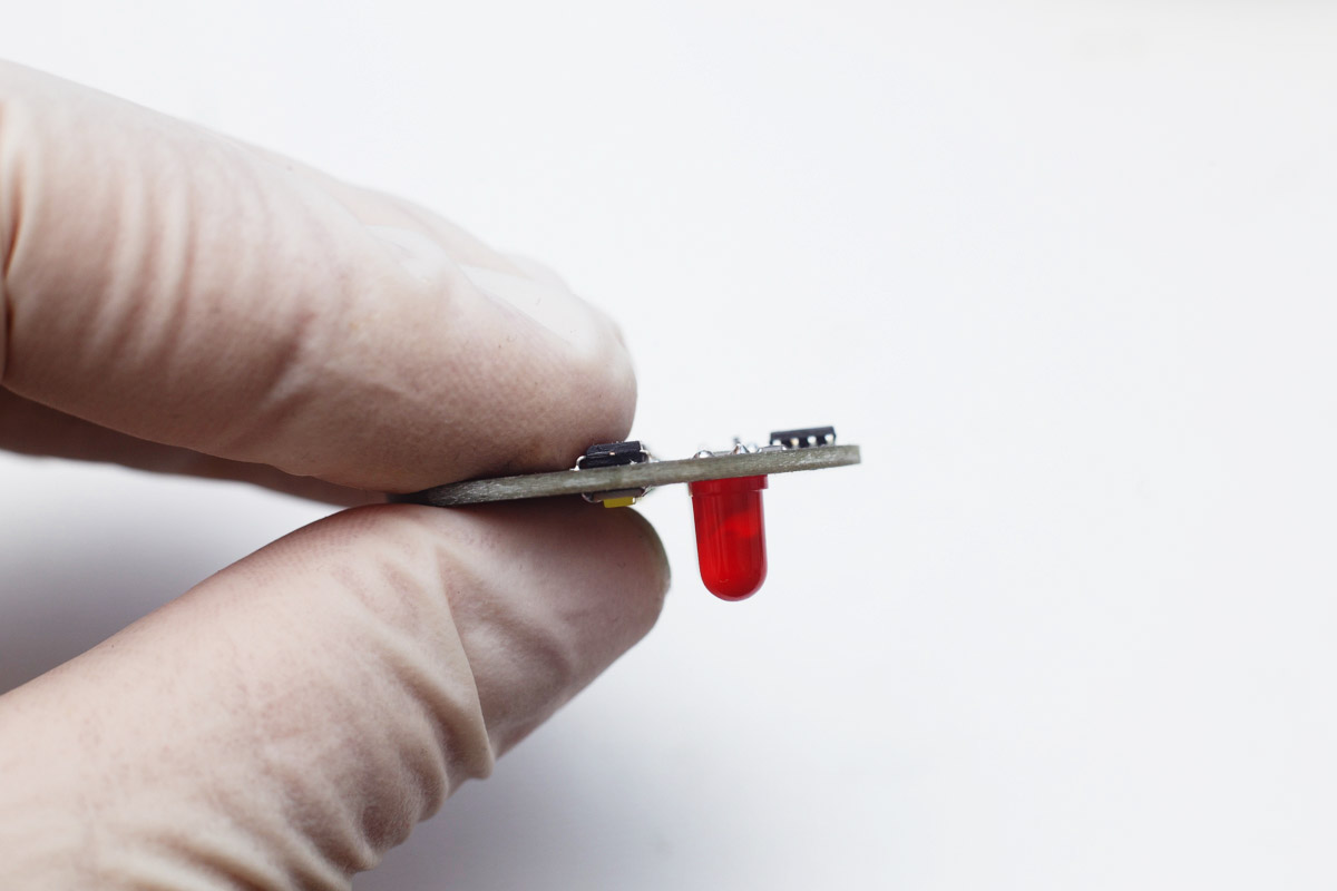
Turn the PCB upside down and solder the first digit LED (the first from the right), the polarity is important (see the photo).
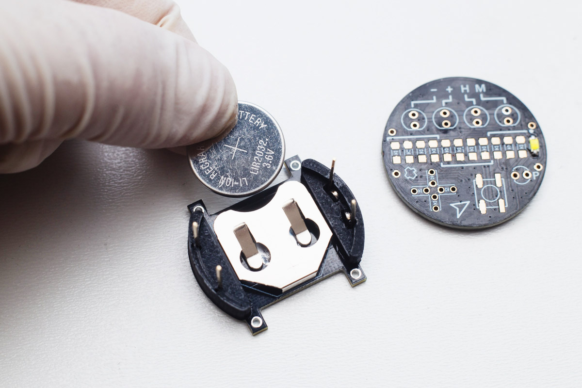
Now it's the testing time! Insert the battery as shown in the photo and put the watchface onto the base. The LED should light up for a while, then blink few times and then turn off. Check the video. If not working correctly, check all contacts and try again...
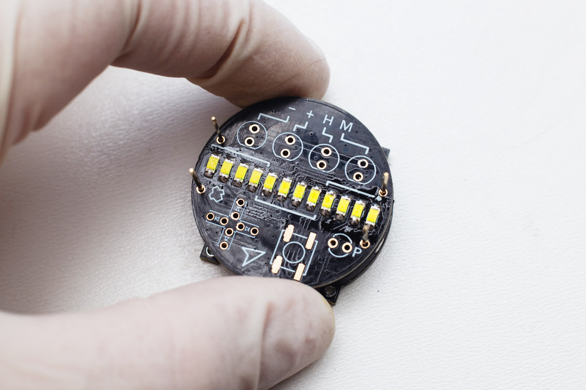
If everything's OK, remove the watchface from the base, solder the rest of digits, and check the functionality.
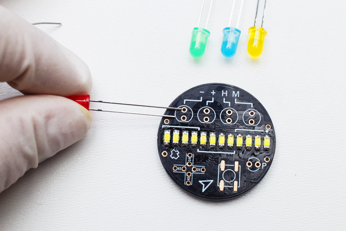
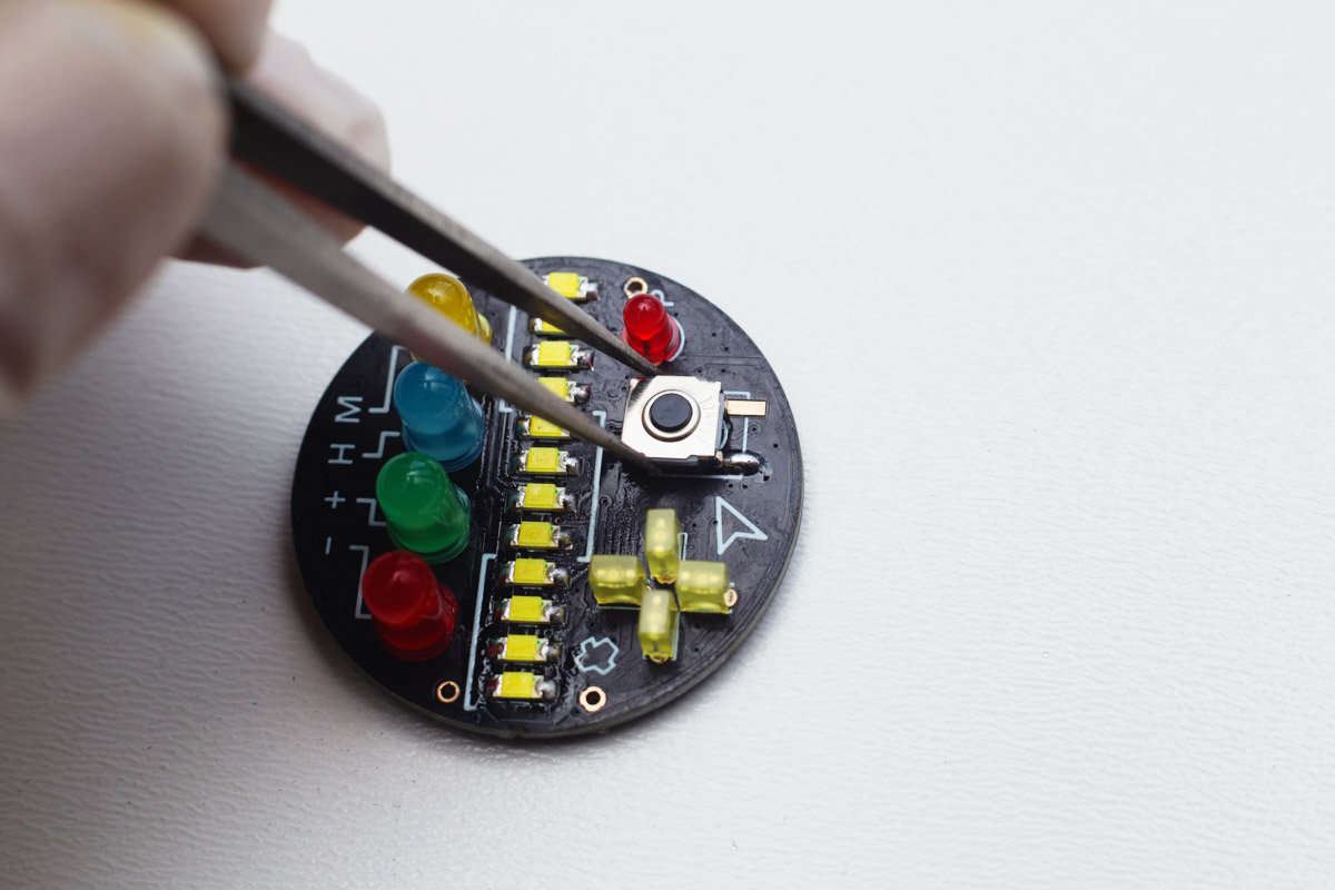
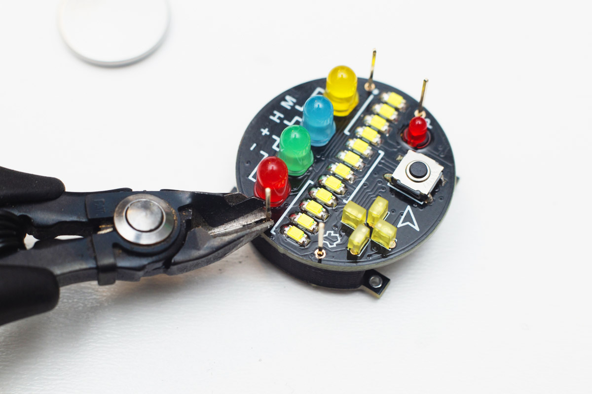
Then, solder the four top LEDs (-, +, H, M). The short leg of an LED goes to the "flat" side, as shown in the photo. Put all LEDs inside, turn the PCB upside down, solder one leg of each LED, check whether it's flush (if not, reheat and make it flush).

Then cut the legs and solder all remaining pads.
The legs shouldn't be higher than ICs to prevent short circuit.
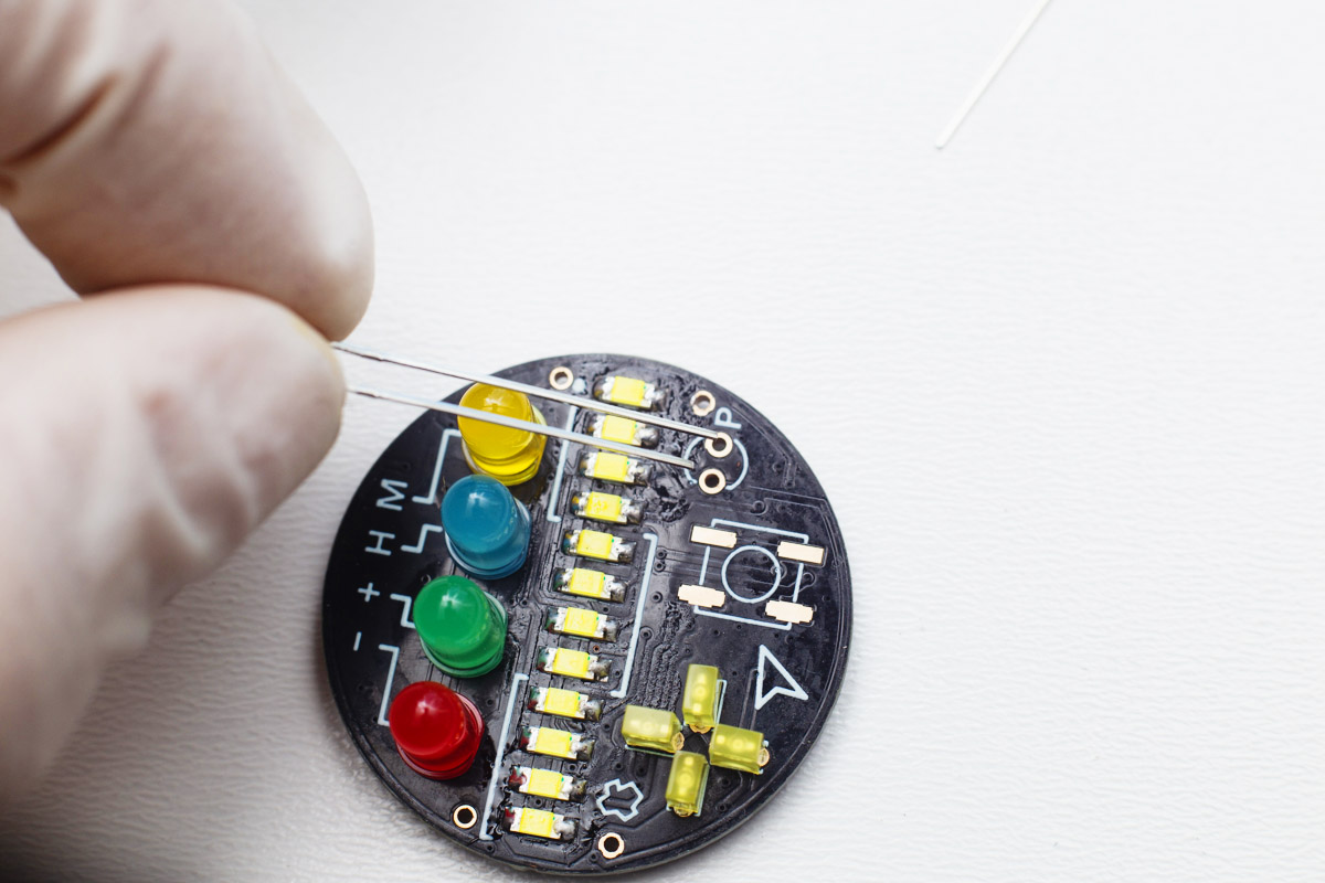
Then solder the yellow rectangle through-hole LEDs showing hour fractions. The long leg of each LED should be closer to thecenter as shown in the picture.
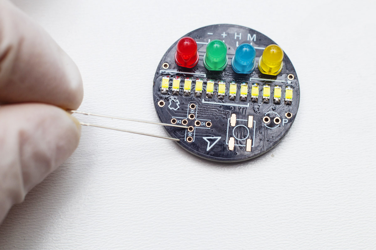
Then solder the "P" LED, short leg goes to the flat side again.
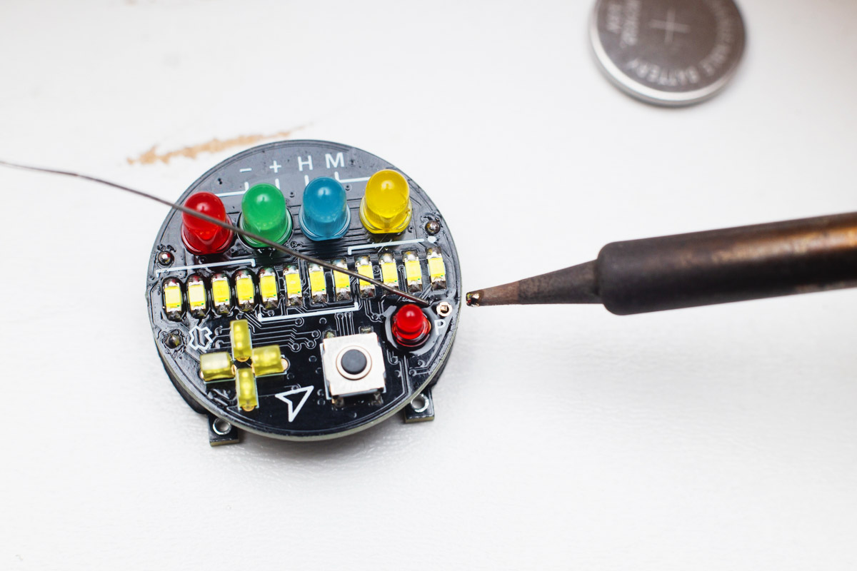
Again, tin one pad and solder the button.
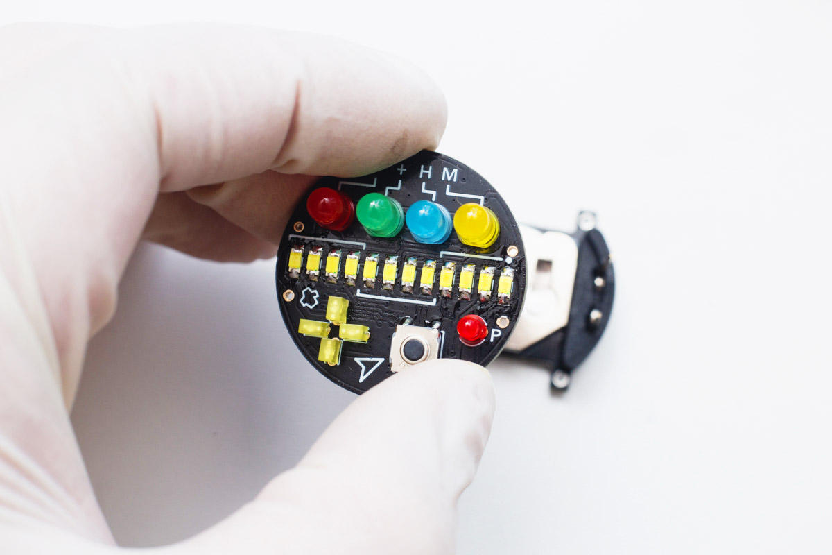
Now, the watchface is ready. Test it against the video below whether everything works as should.
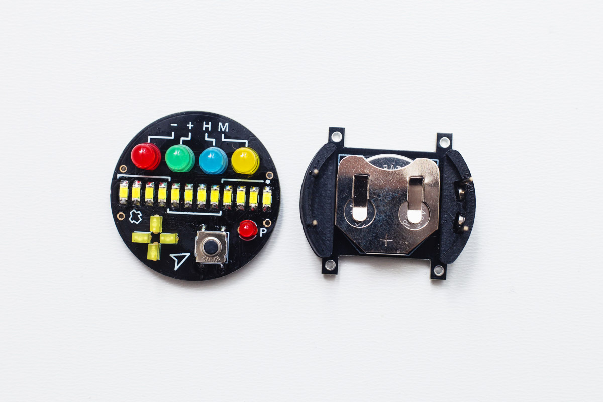
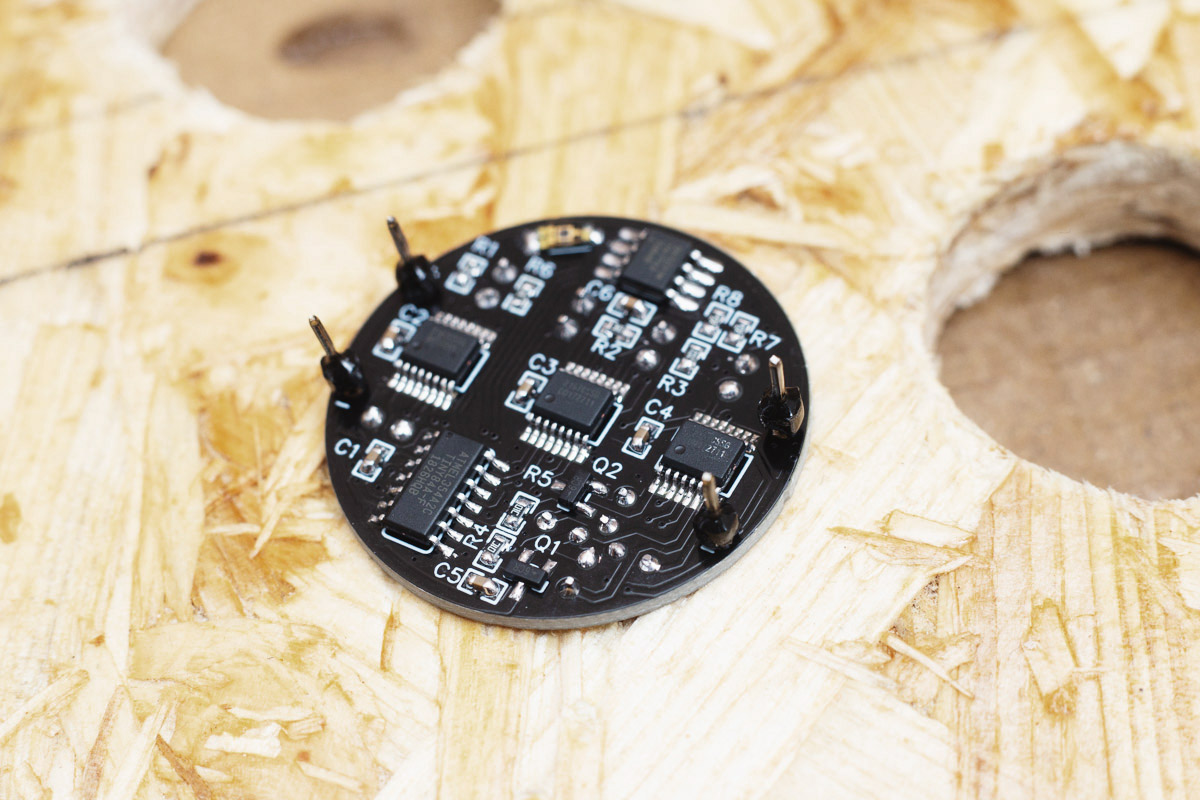
When everything's OK, pull the battery out. We will be finishing the charging contacts.
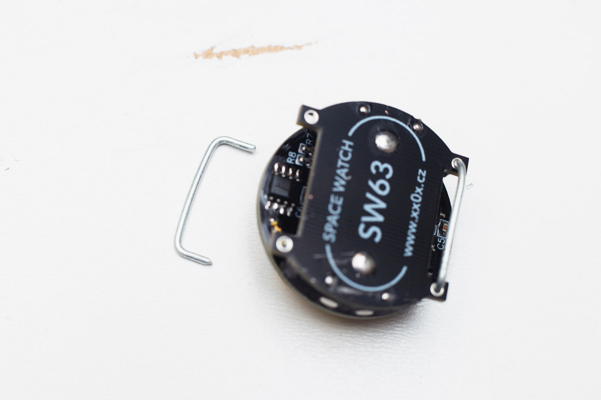
Charging contacts
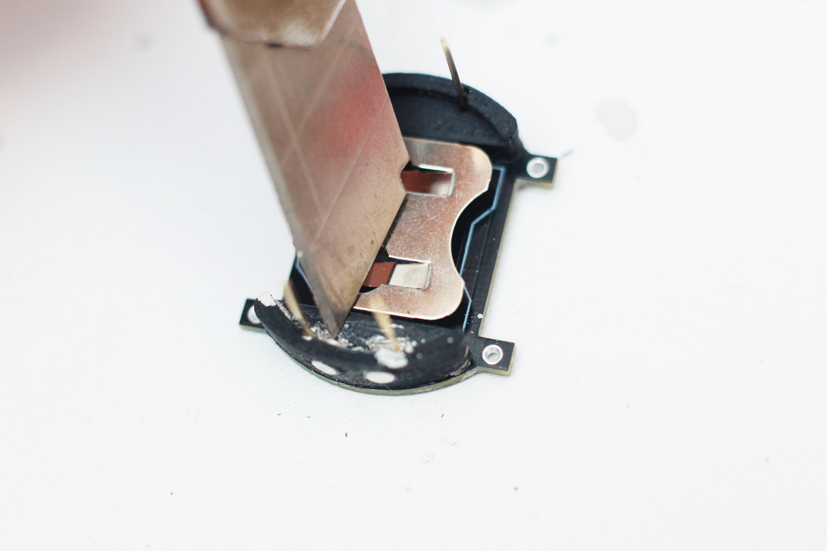
Cut short pieces of solder and press them into the two "holes" for magnets to make contact with the support wires. See the pictures how to do that.
Test the continuity using multimeter, that both magnets are connected with the wires in line with them.
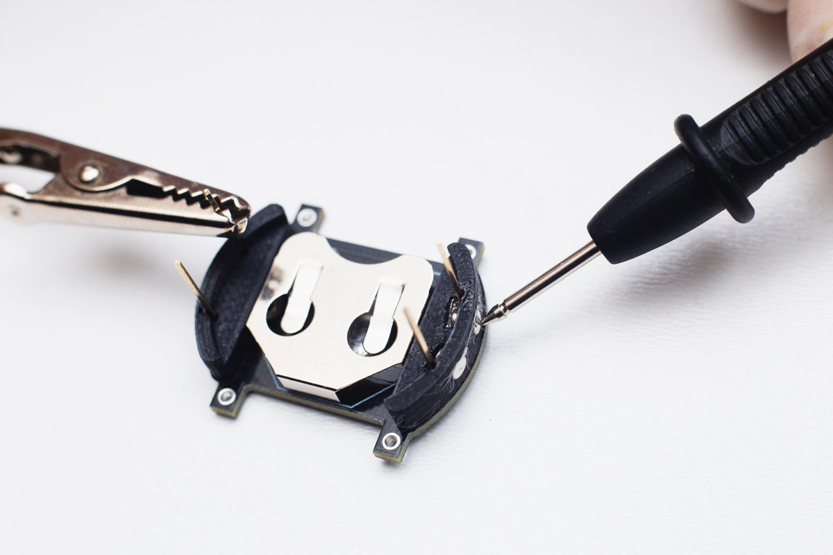
Next step it's not necessary, but highly recommended. Put some silver based (not carbon based!) glue using sharp skewer onto the contacts for better and long lasting connection.
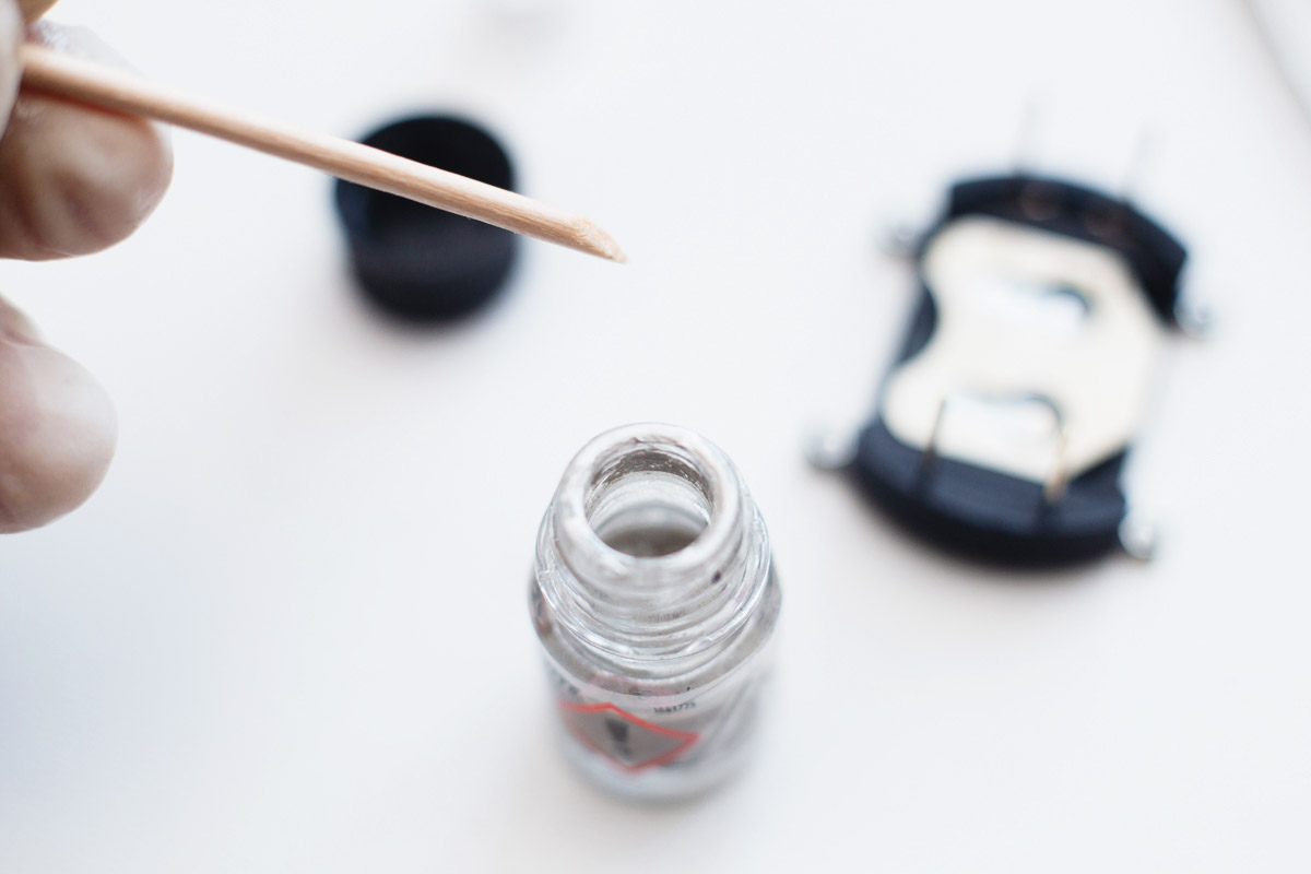

Let it dry for a while, then using sharp blade scrape the excess glue if any.
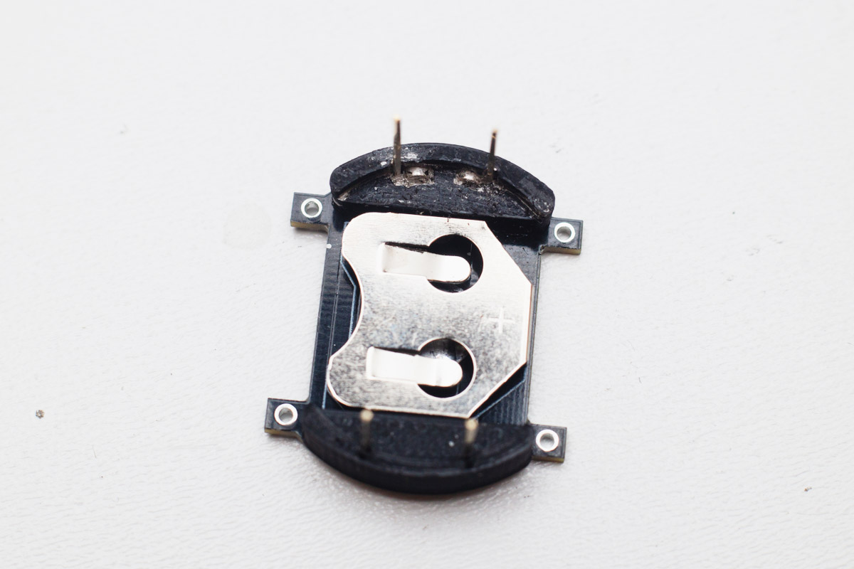
The result should look like this.
Cleaning the watchface
Using an rubbing alcohol (ethanol, IPA), clean the flux remainings from the watchface. Finish with distilled water, to prevent white alcohol marks. Don't worry about the button, it's IP67 resistant.
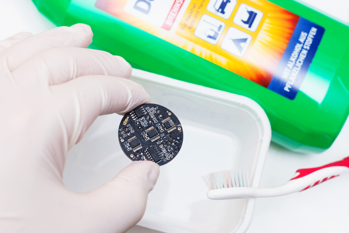
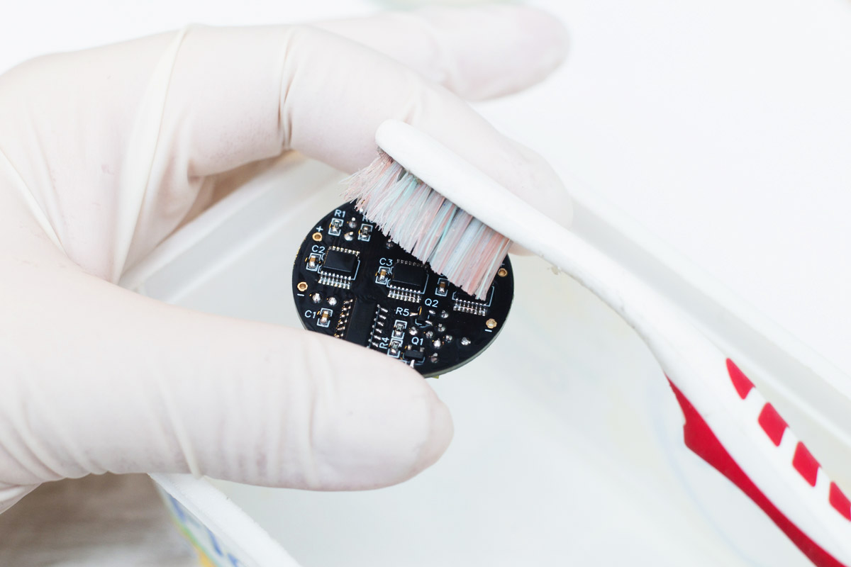
Let the PCB dry, you can use hairdryer for that.
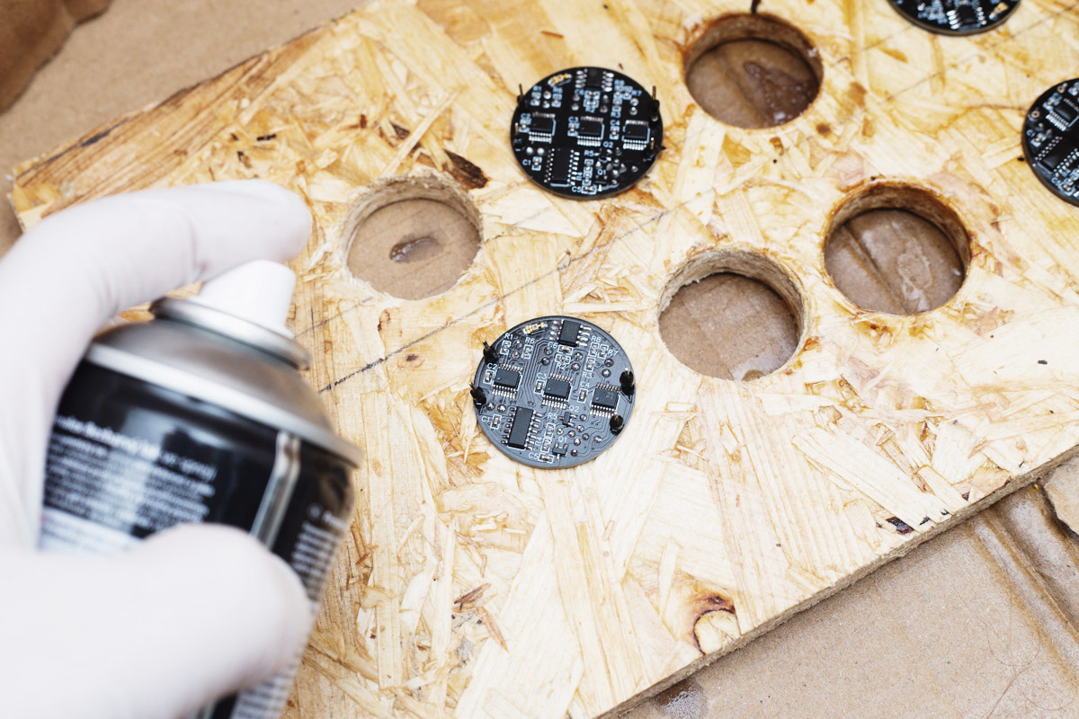
Spraying the watchface bottom
Next step is not necessary, but recommended. Since the case is open and waterdrops can get inside and while not making damage, it can reset the time etc. Therefore, coating the bottom with clear warnish is recommended.
Use header pins to prevent the varnish flowing into the four remaining PCB holes.
Assembly continues
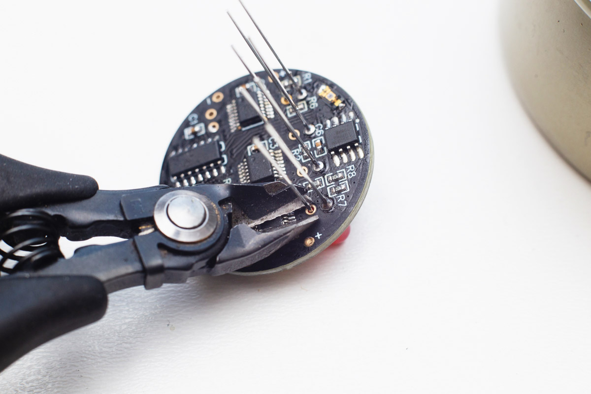
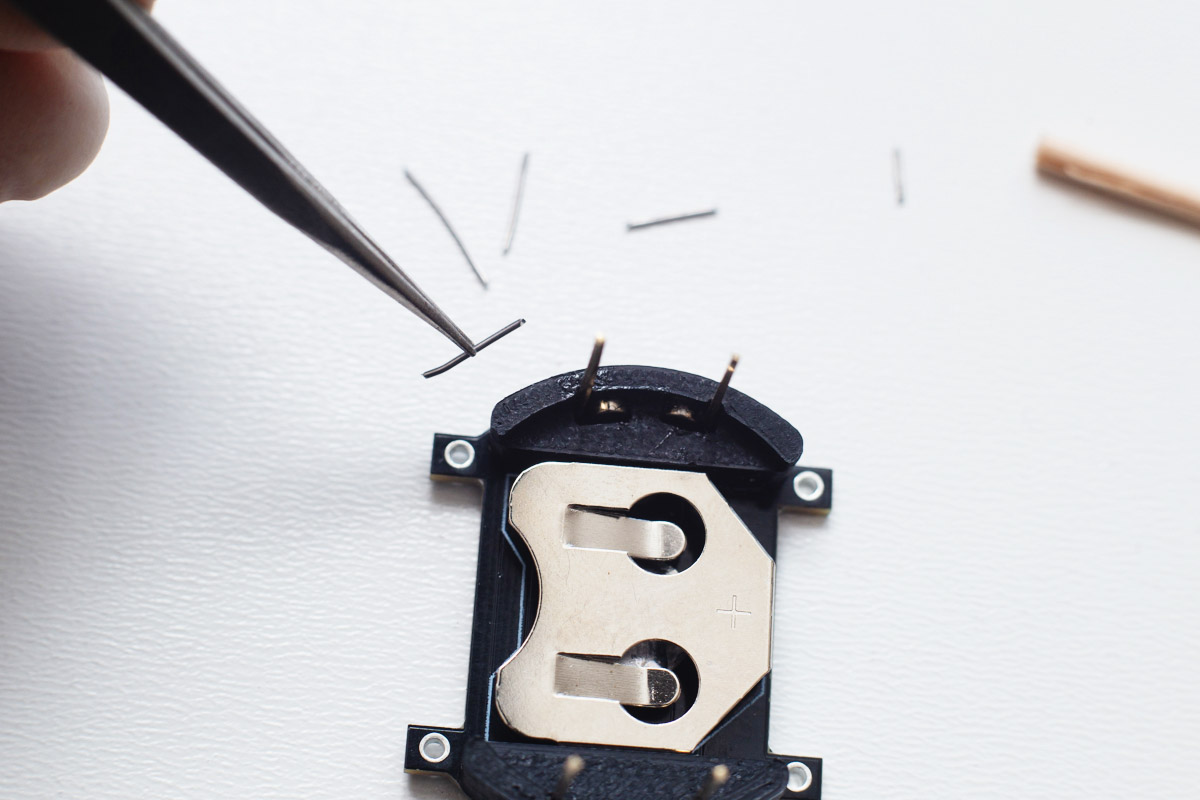
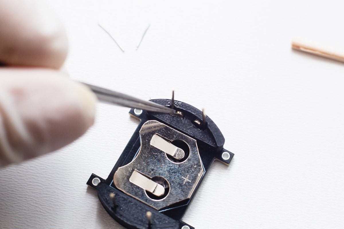
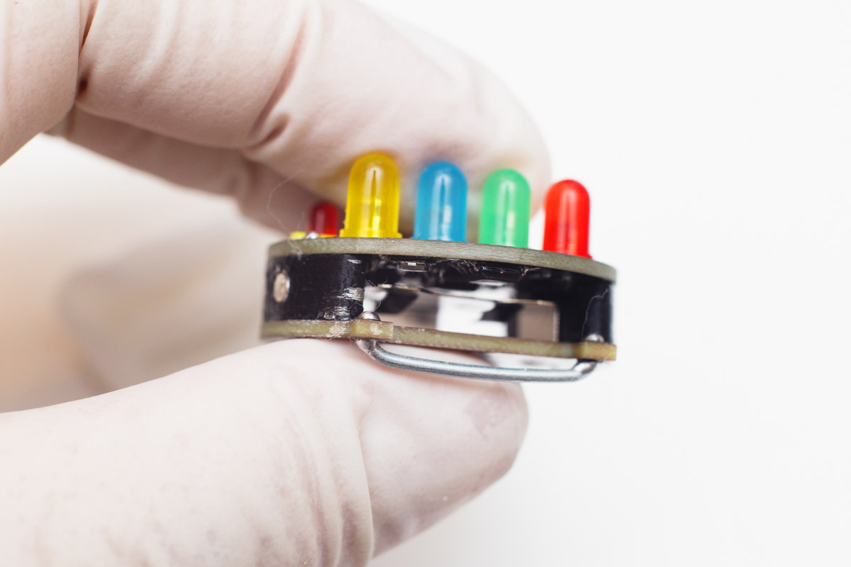
Puth the watchface on the base and shorten the support wires, then solder it.
Using pliers, make two U-shaped parts from supplied thick wire.
Solder them as shown in the picture.
Pull the watchband trough it...
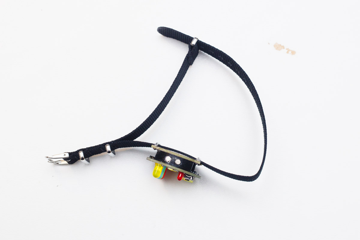
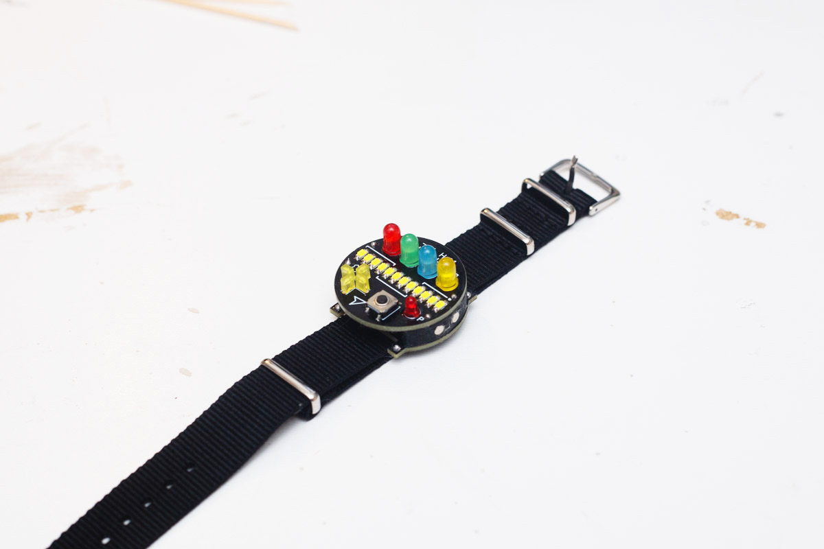
...put the battery inside, and the watch is ready!
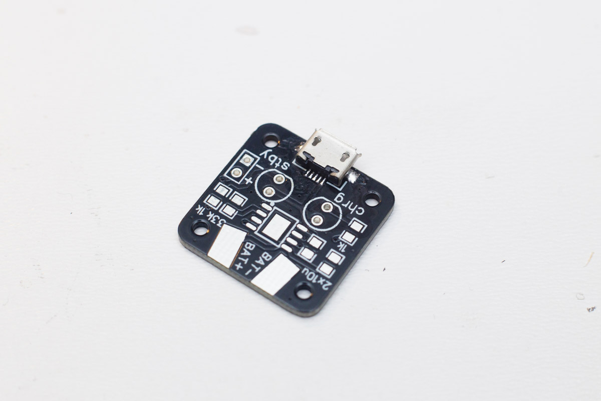
Building the charger
Pull all of the charger components on the table.

First, solder the micro USB connector. Start with the side pads, then solder the five contacts. Lots of flux will help you.
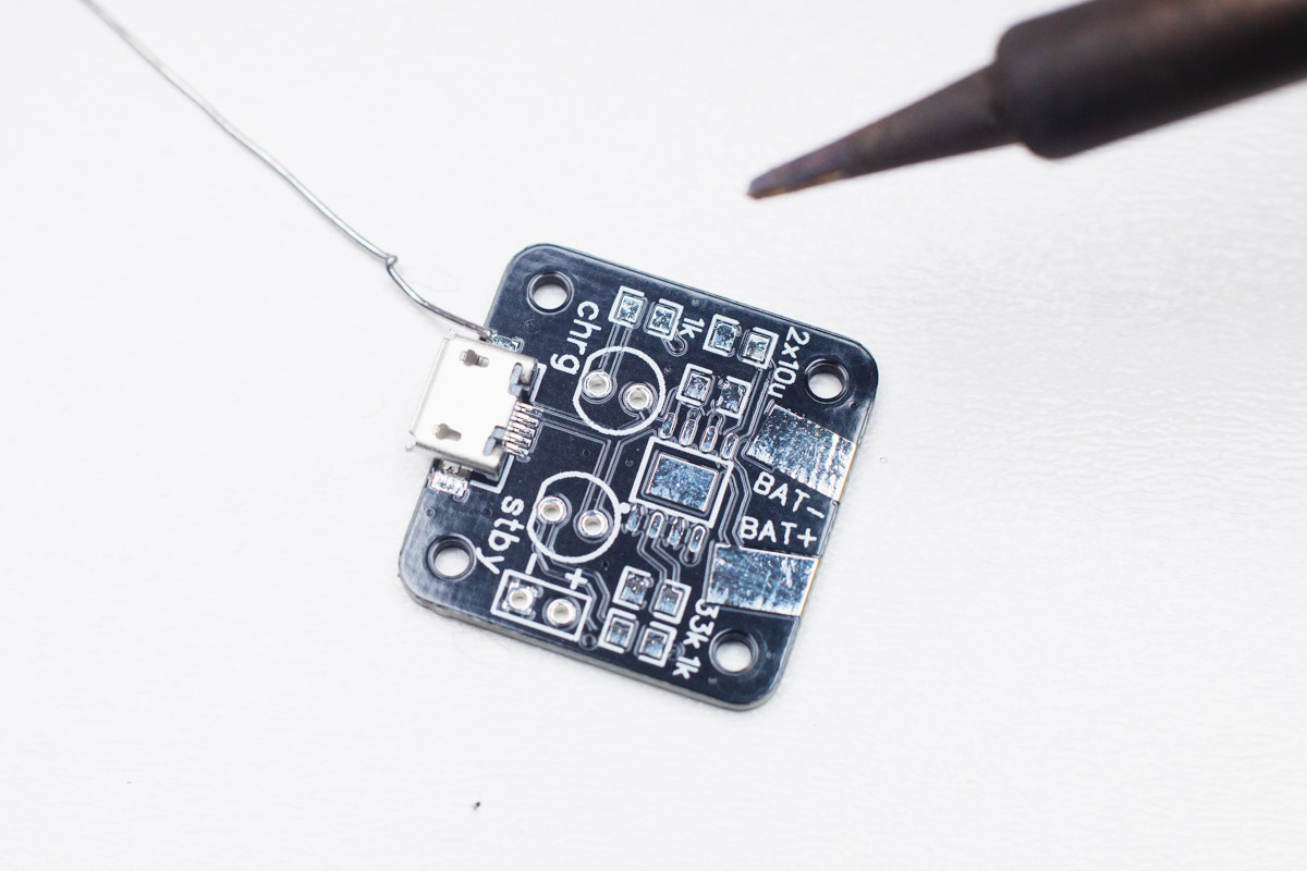
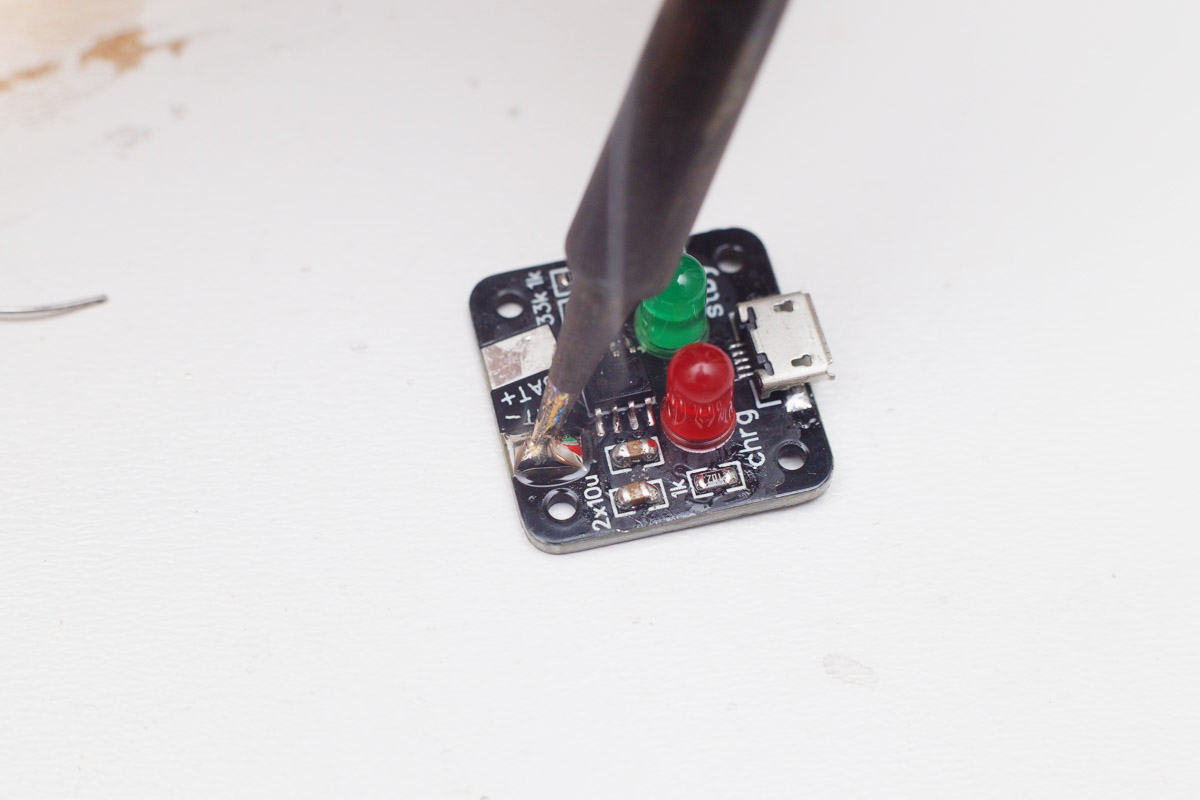
Then solder the charging IC, again start with one pad and keep in mind the orientation (dot).

Solder the capacitors (both 10u), and resistors (2 × 1k, 1 × 33k), the orientation doesn't matter.
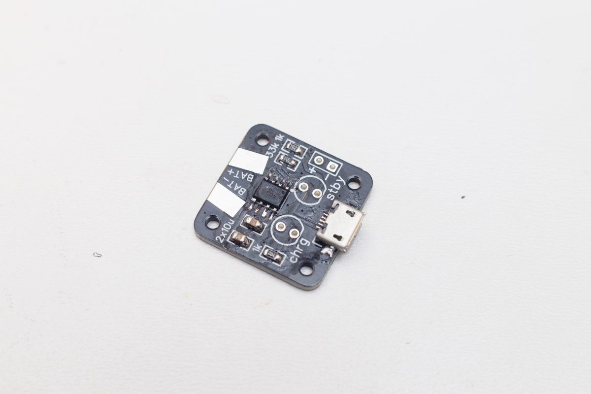
Solder the LEDs, the short leg goes to the flat side.
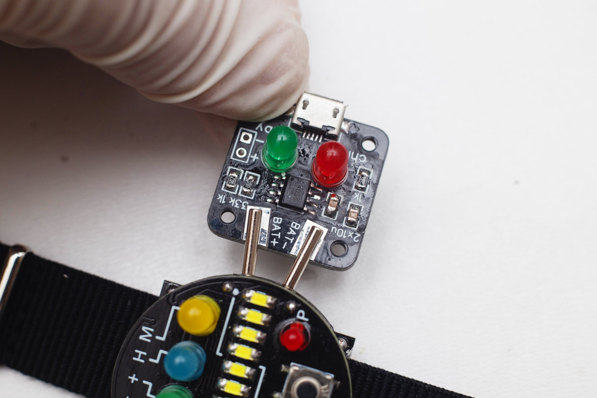
Connect a micro USB cable and test the charger. Green LED (stby) should be solid, red LED (chrg) should flash ("battery not connected").

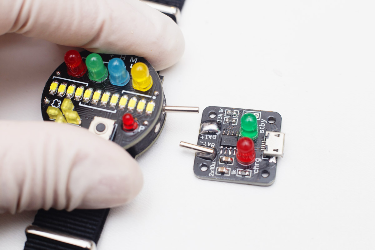
After, put the magnets onto the watch contacts and try whether the aligment is OK.
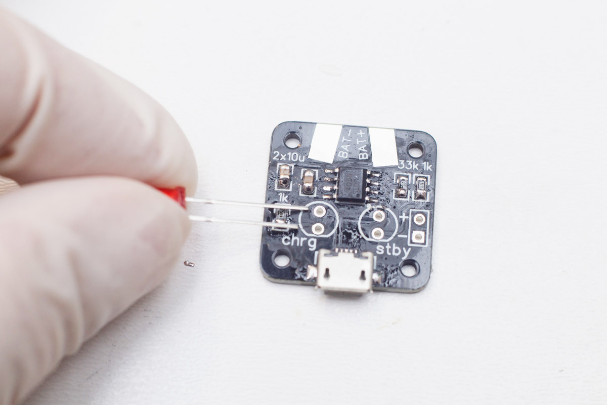
Put a BIG blob of solder on one BAT pad and while it's still hot, guide the charger to the magnets.
Then, make a BIG blob on the second BAT pad and while still hot, align the second magnet inside. If the aligment is wrong, you can reheat it, but be careful, using a lot of heat can damage both the magnets and the plastic part made from ABS.
Test the charger functionality, then clean the charger the same way you cleaned the watchface. 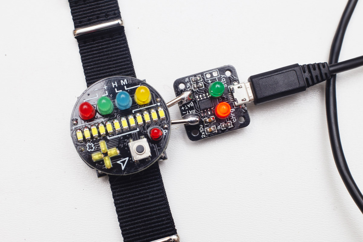
Congratulations!
Your watch is ready!